
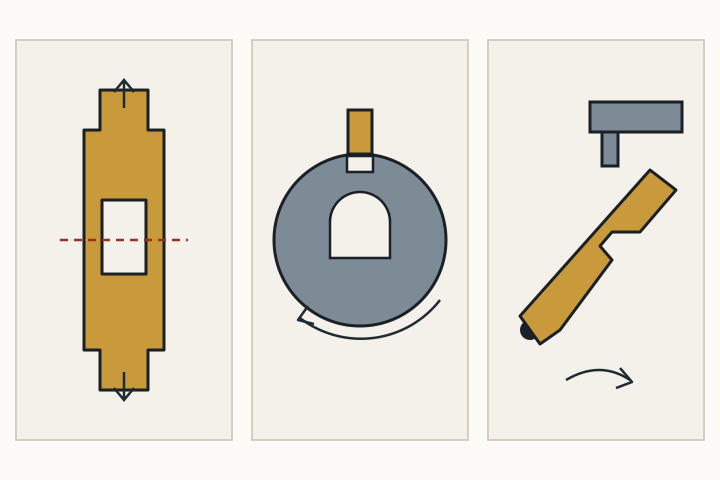
The same question, four answers
The pin tumbler guide described a lock as a machine that answers one question: may the moving part turn or slide right now? In a pin tumbler the answer depends on whether every split between two pins sits on the shear line. Other locks ask the same question with different parts. This guide looks at three of them, each explained from a patent that describes it.
Patents are useful here because they have to explain a mechanism clearly enough for someone else to understand it, and because they usually begin with a background section that describes the ordinary version of the lock before introducing the inventor's improvement. The improvements are not the point of this guide. The ordinary mechanism is.
Wafer locks
A wafer lock replaces each pin stack with a single flat plate. US patent 4015458, filed in 1975, describes a wafer lock with the usual parts: a fixed housing with a bore, a plug that can turn inside it, and a set of flat stamped wafers, one in each slot across the plug.
Each wafer has an opening in the middle, and the key passes through those openings. The edges of that opening are shaped to meet the cuts on the key. Each wafer also has ends that stick out beyond the plug and sit in slots in the housing. As long as any wafer end reaches into the housing, the plug is held in place.
When the right key is inserted, each cut moves its wafer to the one position where neither end sticks out past the plug. With every wafer in that position, nothing crosses from the plug into the housing, and the plug can turn. So a wafer does the job of a whole pin stack: instead of two pins meeting at a line, one plate has to be centered within the plug.
The same patent adds a second check called a sidebar. Small T-shaped pieces sit in a channel along the side of the plug, and each has a serrated edge that meets a matching edge on its wafer. With the right key, the wafers move the sidebar pieces out of the way. The principle is the one that runs through this whole site: every extra part that has to be in the right place at the same time is another condition the right key must satisfy. The patent also describes a design that needs no springs, because the key's own movement returns the sidebar pieces.
Rotating disc locks
A disc lock, sometimes called a disc detainer lock, uses parts that turn rather than slide. US patent 3948065, granted in 1976 from a Finnish application, describes the arrangement.
- A fixed outer cylinder surrounds an inner cylinder that can rotate.
- Inside the inner cylinder is a stack of locking discs that turn with the key. Each disc has a notch on its rim.
- A locking bar lies along the stack, between the discs and the outer cylinder. In the locked position the bar sits partly in a groove in the inside wall of the outer cylinder, which keeps the inner cylinder from turning.
The key does not lift anything. As it turns, it rotates each disc by a different amount. With the right key, every notch ends up in the same place, and together the notches form a channel right under the locking bar. The bar moves down into that channel and out of the groove in the outer cylinder, and the inner cylinder is free to turn and work the lock.
The idea is the same as the shear line, turned on its side. In a pin tumbler, many splits have to meet one line. In a disc lock, many notches have to meet one bar. If a single disc is turned too far or not far enough, its rim blocks the bar and nothing moves.
Lever locks
A lever lock moves the bolt directly with the key, rather than turning a plug. US patent 4739639, granted in 1988, opens with a description of the conventional lever lock that is clear enough to follow without drawings.
- The lock contains a stack of flat, pivoted levers, also called lever tumblers, and a sliding bolt.
- A small post called a stump sticks out from the bolt and rides alongside the levers.
- Each lever has a slot cut through it, called a gate or gating, joining two pockets where the stump rests when the bolt is fully in or fully out.
- The key turns in the lock. Steps on the key lift each lever to a set height, and another step pushes the bolt.
The stump can only travel from one pocket to the other through the gates, and it can only do that when the gates in all the levers line up. Each step on the key has to lift its lever by exactly the right amount. A lever lifted too little or too much leaves solid metal in the stump's path, and the bolt cannot move. Once again, every part has to agree at the same moment.
Because the key itself has to lift levers and push the bolt as it turns, a lever lock key looks different from a flat cylinder key: its working part is a set of steps at the end of the shank rather than a row of cuts along a blade. Inside, though, the logic is familiar.
Side by side
| Mechanism | What the key moves | What must line up | What it then frees |
|---|---|---|---|
| Pin tumbler | Pin stacks, lifted | Every split between pins on the shear line | The plug turns |
| Wafer | Flat wafers, slid | Every wafer within the plug, none reaching the housing | The plug turns |
| Rotating disc | Notched discs, rotated | Every notch under the locking bar | The bar drops and the inner cylinder turns |
| Lever | Pivoted levers, lifted | Every gate in the path of the bolt stump | The key pushes the bolt |
The table is the site's own summary of the four patents and the pin tumbler account cited on this page and the previous one. It compares the principle of each mechanism, not how secure any particular product is. Security depends on materials, tolerances, extra features such as sidebars, and how the lock is fitted, which is why the home locks guide relies on tested ratings rather than mechanism type.
Example: reading a lock by its key
Worked example
This describes general shapes only, not any real product. Someone finds three old keys in a drawer and wonders what kind of lock each one belonged to.
- A flat key with cuts along one or both edges could belong to a pin tumbler or a wafer lock. Both use a flat blade that pushes parts up or down as it slides in.
- A key shaped like a half-round rod, with angled cuts at different heights along it, matches the disc lock's principle: it is turned to rotate discs, so its cuts are angles rather than depths.
- A key with a round shank and a small stepped flag at the end matches the lever lock: the steps on the flag lift levers and push the bolt as the key turns.
The shape of a key is a clue to the mechanism, not proof of it. The point of the example is that each key shape follows from the job it does inside the lock.
Where this guide stops
Each mechanism is explained as a patent background or a museum label would explain it. The guide does not describe ways to open any of these locks without the key, and the patents' own discussions of attacks are left out on purpose. The next guide turns from the lock to the key itself: blanks, keyways and who can make a copy.
Next explainer: Keys, key blanks and keyways